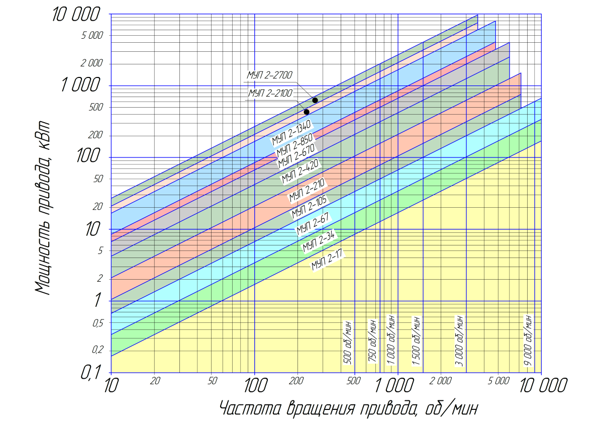
SPECIFICATIONS
|
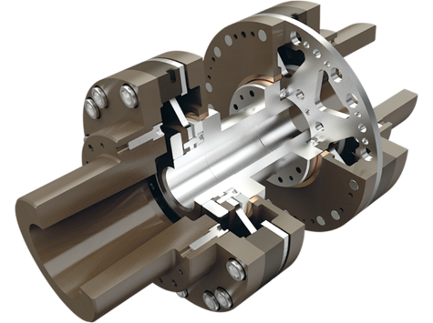
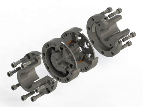
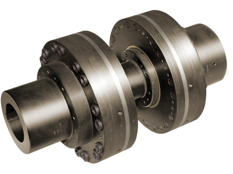
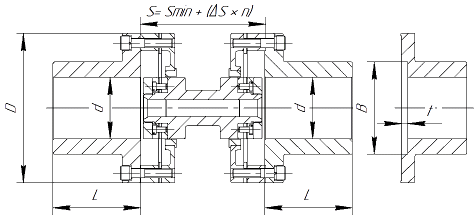
MUP-2 - dimensions |
|||||||
| Coupling nominal size | Standard length of coupling half L, mm | Coupling outer diameter D, mm | The minimum distance between the ends of the shafts Sme, mm | Bore diameter of half-couplings dmax, mm | Transmission unit weight | Weight of unbored coupling half standard, kg | |
| at Sme, kg | +ΔS = 10 mm, kg | ||||||
| MUP 2-17 | 80 | 125 | 110 | 60 | 4,1 | 0,08 | 3,9 |
| MUP 2-34 | 100 | 150 | 125 | 70 | 5,6 | 0,08 | 8,2 |
| MUP 2-67 | 120 | 170 | 130 | 80 | 9,7 | 0,08 | 10,7 |
| MUP 2-105 | 140 | 190 | 130 | 95 | 13,3 | 0,13 | 15,7 |
| MUP 2-210 | 150 | 220 | 150 | 110 | 16,5 | 0,13 | 17,3 |
| MUP 2-420 | 160 | 265 | 165 | 135 | 31,8 | 0,31 | 28,0 |
| MUP 2-670 | 180 | 290 | 175 | 150 | 40,0 | 0,31 | 33,0 |
| MUP 2-850 | 200 | 295 | 190 | 150 | 46,0 | 0,26 | 39,0 |
| MUP 2-1340 | 200 | 320 | 200 | 160 | 57,0 | 0,49 | 52,0 |
| MUP 2-2100 | 200 | 365 | 240 | 180 | 82,0 | 0,54 | 56,0 |
| MUP 2-2700 | 220 | 385 | 250 | 200 | 92,0 | 0,57 | 65,0 |
*Transmission unit length S performed, starting from size Smin and more in steps ΔS = 10mm., other sizes depending on the distance between the shafts are available on request. Length of half couplings L may differ from the standard, subject to filling out the questionnaire. dimensions AT and t pockets for fastening the coupling half with a nut are provided upon request when filling out the questionnaire.
Note: To determine the mass of the coupling assembly, it is necessary to add the mass of the two coupling halves with the mass of the transmission unit.. If not specified, the size of the cylindrical bore of the half couplings is made with an accuracy of H7 and the keyways Js9 are made according to DIN standards 6885.
| MUP-2 - technical data | ||||||||
| Coupling nominal size | Specific power kW / 1000rpm | Torque, Nm | Maksim. turnovers, rpm | Maksim. revolutions without balancing, rpm | Max. axial displacement | Max. radial displacement, ±мм | ||
| Nominal, Nm | Peak overload, Nm | ± mm | Equivalent. an effort, n | |||||
| MUP 2-17 | 17 | 160 | 395 | 18000 | 10000 | 1,5 | 650 | 0,25 |
| MUP 2-34 | 34 | 315 | 787 | 15000 | 8500 | 1,7 | 720 | 0,30 |
| MUP 2-67 | 67 | 630 | 1575 | 13000 | 7500 | 2,0 | 800 | 0,35 |
| MUP 2-105 | 105 | 1000 | 2500 | 12000 | 6500 | 2,2 | 1500 | 0,40 |
| MUP 2-210 | 210 | 1950 | 4875 | 10000 | 5500 | 2,4 | 3050 | 0,45 |
| MUP 2-420 | 420 | 4000 | 10000 | 8500 | 4600 | 2,6 | 4600 | 0,50 |
| MUP 2-670 | 670 | 6300 | 15750 | 7500 | 4200 | 3,4 | 5700 | 0,60 |
| MUP 2-850 | 850 | 8050 | 20125 | 7500 | 4200 | 3,4 | 7800 | 0,60 |
| MUP 2-1340 | 1340 | 12500 | 31250 | 7000 | 3800 | 3,8 | 9600 | 0,60 |
| MUP 2-2100 | 2100 | 19500 | 48750 | 6000 | 3400 | 4,0 | 10100 | 0,60 |
| MUP 2-2700 | 2700 | 25650 | 64125 | 5800 | 3200 | 4,0 | 12500 | 0,60 |